

Helical Pile Design Guide: Capacity, Specs and a Worked Example
Helical pile design guide: IBC 1810 and AC358 basis, bearing vs cylindrical shear, Kt torque, 3D helix spacing, embedment, specs and a worked example.

Helical pile design means showing that each pile's allowable load is the lowest of several limits: soil capacity from bearing theory, capacity from installation torque, load test results, and the strength of the shaft, couplings, helix plates and bracket. In the U.S. the framework is IBC Section 1810.3.3.1.9 plus ICC-ES AC358. Standard practice divides ultimate capacity by a factor of safety of at least 2, spaces helix plates three diameters apart, and sets a minimum installation torque every production pile must reach.
Key takeaways
- Least of several limits: Allowable capacity is the lowest of bearing theory, torque correlation, load tests, shaft and coupling strength, helix plate strength and bracket strength.
- Factor of safety: Geotechnical capacity is ultimate divided by at least 2.0. Under the IRC with no geotechnical report, one evaluation report requires 2.5 with torque correlation.
- Two bearing models: Helices spaced at 3D or more are designed by individual plate bearing. Closer spacing is designed by cylindrical (perimeter) shear.
- Torque is the field check: Qult = Kt × T, with Kt from 10 for 1.5 to 1.75 inch square shafts down to 5.5 for a 4.5 inch pipe shaft.
- Depth rules: Top helix at least 5D deep for compression in one manufacturer's guidance, and 12D for tension under AC358-based reports.
- Soft soil: Unbraced length grows by 10 feet in soft soil (SPT N under 5), and square shafts add little lateral resistance.
The design basis: IBC Section 1810, AC358 and evaluation reports
The allowable axial load is set by Section 1810.3.3.1.9, which lists the capacities a designer must compare. The CHANCE evaluation report ESR-2794 (reissued May 2026, covering the 2009 to 2024 IBC) restates it as the least of:
- Individual helix bearing capacity, divided by the factor of safety.
- Torque correlation capacity.
- Load test ultimate capacity, divided by at least 2.0 (tests per Section 1810.3.3.1.2 under the 2021 and 2024 IBC).
- Allowable capacity of the shaft and couplings, the sum of the helix plates, and the bracket or pile cap.
The 2021 and 2024 editions changed one item. Bearing capacity is now the helix area times the ultimate bearing capacity of the soil or rock plus shaft resistance, which is the shaft surface area above the top helix times the ultimate skin friction. Older editions counted only the plates. The same report ties installation to IBC Section 1810.4.11 and requires continuous special inspection under Section 1705.9.
ICC-ES AC358 and what an evaluation report covers
ICC-ES AC358, Helical Pile Systems and Devices, is the protocol manufacturers test to for an evaluation report; the current edition is AC358(24). A report such as ESR-2794 publishes nominal, LRFD and ASD strengths for the bracket, shaft, couplings and helices, plus torque factors. It does not give soil capacity for your site, and it requires a site-specific geotechnical report covering borings, groundwater, frost depth, corrosion parameters, soil strength, group effects and load testing. Our guide to helical pile ICC-ES evaluation reports explains how to read one, and helical pile permits and building codes covers local adoption.
ASD vs LRFD and factors of safety
Structural strengths are published three ways. For the CHANCE RS2875.203 shaft (2-7/8 inch OD), the manufacturer tech sheet lists tension strength as 60 kip nominal, 45 kip LRFD design and 30 kip ASD allowable. That is a resistance factor of 0.75 and a safety factor of 2.0. Geotechnical capacity is usually handled in ASD.
| Check | How allowable is found | Source |
|---|---|---|
| Bearing method or load test | Ultimate ÷ FS, with FS at least 2.0 | ESR-2794 Sec. 4.1.5 |
| Torque correlation (IBC) | Qall = 0.5 Qult | ESR-2794 Eq. 4 |
| Torque correlation (IRC, no geotechnical report) | Qall = 0.4 Qult (FS 2.5) | ESR-2794 Eq. 5 |
| Permanent vs temporary loading | FS 2.0 permanent, 1.5 temporary (manufacturer minimum) | CHANCE design manual Sec. 5.4 |
| Shaft, couplings, helix, bracket | Published nominal, LRFD and ASD strengths | Evaluation report tables |
Axial capacity: individual bearing, cylindrical shear and torque
Designs use theory or load tests to choose helices and length, then torque to confirm each pile. ESR-2794 requires torque-predicted capacity during production to equal or exceed the capacity from the bearing method or load tests.
Individual plate bearing
Each helix is treated as a small deep footing. Its capacity is the projected helix area times the unit bearing capacity of the soil at that depth, and the plates are summed: Qtot = Σ(Ah qu), where qu = cNc + q′Nq. The CHANCE Technical Design Manual drops the width term because helix plates are small, and uses Nc = 9 for deep helices in clay.
Cylindrical (perimeter) shear
When helices sit closer than three diameters, the soil between them moves as one block. Capacity is then end bearing on the lead helix (bottom plate in compression, top plate in tension) plus shear along the cylinder of soil between the top and bottom plates. The CHANCE manual uses individual bearing for spacing-to-diameter ratios of 3 or more and perimeter shear below 3. A 2026 Hubbell technical review notes that the lower of the two predictions controls.
Torque correlation (Kt)
The empirical method is Qult = Kt × T, with default factors from ESR-2794 below. For multi-helix piles and all tension piles, T is the average of the last three readings taken at 1-foot intervals over the final 2 feet. For a single-helix compression pile, it is the final reading. Charts are in our helical pile torque to capacity chart.
| CHANCE model (shaft) | Kt (ft-1) |
|---|---|
| SS5 (1.5 in. square) and SS175 (1.75 in. square) | 10 |
| RS2875.203 and RS2875.276 (2-7/8 in. pipe) | 9 |
| RS3500 and SS175/RS3500 combo (3.5 in. pipe) | 7 |
| RS4500 (4.5 in. pipe) | 5.5 |
ESR-2794 requires the pile to advance at least 2.5 inches per revolution at final torque, rotation under 25 rpm, a drive motor rated at least 10 percent above the pile's maximum torque, and torque measurement accurate to ±10 percent. Per the design manual, Kt can range from 3 to 20, and soft or sensitive soils need load tests to set it.
Helix spacing: why 3D is the standard
Most U.S. manufacturers build lead sections with plates spaced three times the diameter of the lower helix. An 8-10-12 inch lead therefore has 24 inches between the 8 and 10 inch plates and 30 inches between the 10 and 12 inch plates.
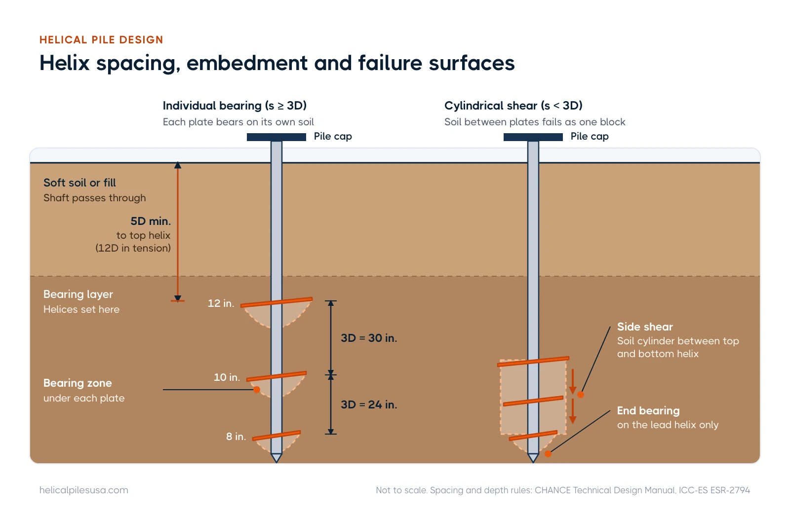
The reason is stress overlap. Hubbell's technical review reports that soil stress one helix diameter from a plate is about 28 percent of the peak, falling to about 4 percent at three diameters. At 3D each plate bears on mostly undisturbed soil, so individual bearing applies. Wider spacing adds shaft length for little gain. Pile-to-pile spacing is a separate question, covered below and in how far apart helical piers need to be.
Minimum embedment and critical depth
A helix too near the surface fails in a shallow breakout mode. The CHANCE design manual recommends the top helix sit at least 5D below the surface (D is the largest helix), with 6D to 8D as standard practice. It also recommends the top helix be at least 3D below any zone of seasonal change such as frost or wetting and drying. For tension, AC358-based reports are stricter: ESR-2794 requires 12D from the ground surface to the top helix.
Critical depth is the opposite limit: in sands, theory says capacity keeps rising with overburden, but field capacity levels off. The manual recommends a critical depth of 20D to 30D into the bearing stratum in loose, saturated soils. See how deep helical piles go for typical project depths.
| Depth rule | Value | For a 12 in. top helix |
|---|---|---|
| Minimum to top helix, compression (manufacturer) | 5D | 5 ft |
| Standard practice, compression | 6D to 8D | 6 to 8 ft |
| Below seasonal frost or moisture zone | 3D | 3 ft below that zone |
| Minimum to top helix, tension (ESR-2794) | 12D | 12 ft |
| Critical depth into loose saturated bearing soil | 20D to 30D | 20 to 30 ft |
Lateral capacity and buckling in soft soils
The CHANCE manual states that square shaft piles do not provide significant lateral resistance, while round (pipe) shafts can. ESR-2794 lists an allowable lateral soil capacity of 1,606 lb for an RS2875.203 pile installed at least 15 feet into stiff clay with SPT N of 26 or more. Other soils need site-specific analysis (Broms' method or finite-difference software), and enlarged upper shafts are used when lateral load governs.
Buckling is mostly a soft-soil problem. ESR-2794 defines firm soil as SPT N of 5 or more, soft soil as N greater than 0 and less than 5, and fluid soil as N of 0. The unbraced length is the length standing in air, water or fluid soil plus 5 feet in firm soil or 10 feet in soft soil, and published compression strengths drop accordingly. For the RS2875.203, the tech sheet lists 62.1 kip LRFD design compression for a fixed head in firm soil versus 49.9 kip in soft soil. The manual flags three cases for a full buckling check: long piles through very soft clay to a hard end-bearing layer, liquefiable loose sand, and eccentric loads without bracing. Pile heads must be braced per IBC Section 1810.2.2, by grade beams, slabs or groups of three or more.
Corrosion allowance
Published strengths include corrosion. ESR-2794 tables allow for 50 years of section loss on hot-dip galvanized steel. Galvanizing is to ASTM A153 Class B-1, at 3.1 mil minimum. Bare steel and galvanized parts may not be mixed in one system unless the galvanized parts are designed with the bare-steel sacrificial thickness of 0.036 inch, and all components must be isolated from rebar and structural steel.
The report also sets limits. Soil resistivity under 1,000 ohm-cm, pH under 5.5, high organic content, sulfates over 1,000 ppm, landfills and mine waste are outside its scope and need a corrosion-specific design. Our guide do helical piers rust covers coatings and service life in more detail.
Group effects and pile spacing
ESR-2794 sets a minimum center-to-center spacing of four times the largest helix diameter. Closer spacing requires the geotechnical report to state group load reductions, which the designer must apply. The CHANCE manual recommends five diameters (3 feet absolute minimum), battering shafts where heads must be close, and a dense bearing layer when spacing is under 4 feet, since group reduction has never been accurately measured for helical piles.
Load testing
Static tests follow ASTM D1143 for axial compression, ASTM D3689 for axial tension and ASTM D3966 for lateral load. Tests verify capacity and can calibrate a site-specific Kt. Under the 2021 and 2024 IBC, load tests used for capacity must meet Section 1810.3.3.1.2, and the result is divided by a factor of safety of at least 2.0.
A typical acceptance criterion from a GoliathTech model specification loads the pile to 200 percent of design load and requires no more than 1 inch of pile head movement at 1.0 times design load, with no failure at 2.0 times. Our guide to helical pile load testing covers procedures and failure definitions.
Worked example: helical piles for a new two-story house
This example follows Design Example 3 in the CHANCE Technical Design Manual (Edition 3), with the torque limit updated to the current ESR-2794. The house is a two-story, slab-on-grade, masonry and wood-frame structure 30 feet wide, founded in clay with an SPT N of 16.
| Step | Calculation | Result |
|---|---|---|
| 1. Line load on perimeter footing | 1,540 DL + 346 LL + 162 SL | 2,048 lb/ft |
| 2. Working load per pile | 6.0 ft spacing × 2,048 lb/ft | 12,288 lb |
| 3. Required ultimate at FS 2.0 | 2 × 12,288 | 24,576 lb |
| 4. Pile and helices | RS2875.203, 8-10-12 in. lead | Areas 0.34 + 0.53 + 0.77 = 1.64 ft² |
| 5. Helix spacing (3D of lower helix) | 3 × 8 in.; 3 × 10 in. | 24 in. and 30 in. |
| 6. Soil strength | c from N = 16; Nc = 9 | c = 2,000 psf |
| 7. Ultimate by individual bearing | 1.64 × 2,000 × 9 | 29,520 lb |
| 8. Factor of safety by bearing | 29,520 ÷ 12,288 | 2.4 (OK) |
| 9. Required installation torque, Kt = 9 | 24,576 ÷ 9 | About 2,730 ft-lb (manual rounds to 2,750) |
| 10. Torque limit check | 2,730 vs 6,710 ft-lb max for RS2875.203 leads in ESR-2794 | OK |
| 11. Pile spacing check | 72 in. vs 4D = 48 in. (ESR) and 5D = 60 in. (manual) | OK |
| 12. Minimum embedment | 5D = 5 × 12 in. to top helix | 5 ft minimum; manual example installs past 20 ft |
If the crew cannot reach about 2,730 ft-lb at the planned depth, the manual gives two fixes: tighten pile spacing to reduce load per pile, or move to a larger lead such as 10-12-14 inches. Torque ratings also change between documents: 5,500 ft-lb in the 2014 manual, 7,000 in the 2022 tech sheet and 6,710 in the 2026 ESR lead table. Put the current evaluation report value on permit drawings, and see the helical pile shaft sizes chart for larger shafts.
What goes in a helical pile spec section (31 66 15)
In MasterFormat, helical piles are usually specified under Section 31 66 15, Helical Foundation Piles. The GoliathTech model spec uses that number. Evaluation reports may differ: ESR-2794 lists Section 31 63 00, Bored Piles, and the Canadian CCMC 13193-R report lists 31 62 16.01. Match the number your project manual already uses. A complete section usually has three parts:
- Part 1, General: scope, related sections, referenced codes and ASTM standards, definitions, submittals, manufacturer-certified installer, warranty.
- Part 2, Products: shaft size and steel grade, helix diameter, thickness and pitch, coupling bolts, galvanizing, brackets or caps, and the required evaluation report.
- Part 3, Execution: equipment and calibrated torque indicators, rate and rpm, tolerances, termination criteria, refusal and low-torque options, load testing, inspection and records.
The GoliathTech tolerances are a good start: 3 inches of plan location, 2 degrees of inclination and 2 inches of top elevation.
Submittal and installation-record checklist
Drawing on ESR-2794's design documentation list and the GoliathTech submittals, a reviewer should see:
- Site-specific geotechnical report, including corrosion data and group-effect recommendations.
- Pile layout with ID numbers, design loads (compression, tension, lateral, moment) and load combinations.
- Manufacturer, evaluation report number, catalog numbers for leads, extensions and brackets.
- Shaft size, helix configuration, minimum and maximum tip embedment, cut-off elevation and inclination.
- Minimum effective torque and how it is averaged, plus the maximum installation torque of the pile.
- Capacity calculations showing every limit (bearing, torque, shaft, couplings, helices, bracket) and the factor of safety.
- Corrosion protection and galvanic isolation details, and the bracket or cap connection detail.
- Installer certification, equipment list, torque indicator calibration within one year, and the load test plan.
For each installed pile, the record should show pile ID, catalog numbers, equipment, helix configuration, shaft diameter, final tip depth, torque readings and effective torque, inclination, location and bolt tightness. Both minimum torque and minimum depth must be met before stopping, unless doing so would exceed the pile's torque rating or a maximum depth, or create a safety hazard. See the helical pile installation process.
Find a contractor who can work to an engineered design
Choose an installer certified by the specified manufacturer, with calibrated torque monitoring. You can find a helical pile installer in your state or province, compare products on the helical pile manufacturers page, and use our checklist on how to hire a helical pile contractor. Calculators are on the free tools page.
Frequently asked questions
What factor of safety is used for helical piles?
A minimum of 2.0 on geotechnical capacity is standard, so allowable load is half of ultimate. One evaluation report requires 2.5 when torque correlation is used for IRC structures without a geotechnical report, and one manufacturer recommends 1.5 as the minimum for temporary loads.
Is helical pile capacity based on torque or soil bearing?
Both. Designers size the helices with bearing theory or load tests, then set a minimum installation torque so every production pile proves at least that capacity in the field. The lower of the checks governs.
How deep does the top helix need to be?
Manufacturer guidance for compression is at least five times the largest helix diameter, and AC358-based reports require 12 diameters for tension. Frost and expansive soils can push it deeper.
Do helical piles need special inspection?
Yes, under IBC Section 1705.9 special inspection is continuous during installation. The inspector verifies products, equipment, depth, torque and alignment for every pile.
Last reviewed October 2026 by the Helical Pile USA editorial team. Found an error? Tell us.
Subscribe to our weekly email newsletter
Industry news, featured projects, new products, and installer spotlights from across the helical pile industry, delivered to your inbox.


Latest articles

Get the Helical Pile Industry Brief
New installers, manufacturer news, cost updates, and fresh guides for the U.S. and Canadian helical pile industry. Short, occasional emails. Unsubscribe any time.
