

How Far Apart Should Helical Piers Be? Spacing and Count
Helical pier spacing: 4D minimum between piles, 6 to 9 ft along house walls, deck and crawlspace spacing, and how to count piers from load per foot.
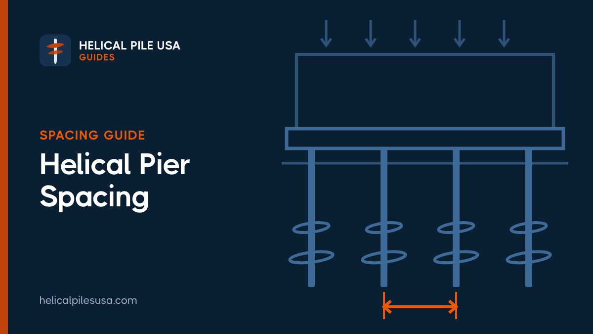

"Helical pier spacing" means two different things. Between piles in a group, the helix plates must sit at least 4 times the largest helix diameter apart, center to center (48 inches for a 12-inch helix), and an engineer has to check group effects below 3 diameters. Along a foundation wall, spacing is set by load: divide the pile's allowable capacity by the wall's load per linear foot, then check that the footing can span the gap. In published manufacturer design examples, that lands between about 6 and 9 feet on center for houses.
Key takeaways
- Group minimum: ICC-ES AC358 and the CHANCE evaluation report ESR-2794 set 4D center to center between helix plates, and require a group-effect analysis below 3D, where D is the largest helix diameter.
- Manufacturer rule of thumb: Hubbell engineers prefer 5D, with an absolute floor of 3 feet.
- Underpinning spacing: pier spacing = allowable pile load ÷ wall line load, capped by how far the footing can span. Block stem walls may only span about 3 to 4 feet; reinforced cast stem walls span about 5 to 9.
- Decks: one pile per post, and post spacing comes from the deck beam span table in IRC Section R507.5.
- Crawlspaces: pier-and-beam support spacing comes from girder load; the Supportworks girder tables cover 4 to 8 feet, and wood girders under a typical floor work at about 5 to 7.
- Point loads: chimneys, columns and corners get their own piers, often more than one, so the footing does not tip.
Two meanings of helical pier spacing
The question "how far apart should helical piers be" has two answers that come from different rules.
- Minimum spacing between piles is a geotechnical limit. Helix plates set too close stress the same block of soil, so each carries less than it would alone. It governs clusters under a column or pile cap.
- Support spacing along a foundation is a structural result. It depends on how heavy the building is, how strong each pile is, and how far the footing or beam can span between supports. This is the number on a repair proposal, and it is almost always much larger than the minimum.
Minimum center-to-center spacing for pile groups
The documents agree on the rule's shape but use different multipliers, all measured from the largest helix plate at bearing depth.
| Rule | Requirement | 10 in. helix | 12 in. helix | 14 in. helix |
|---|---|---|---|---|
| Group analysis trigger (AC358, IBC 1810.2.5) | Analysis required below 3D center to center | 30 in. | 36 in. | 42 in. |
| Minimum plate spacing (AC358, ESR-2794) | At least 4D center to center (3D edge to edge) | 40 in. | 48 in. | 56 in. |
| CHANCE recommended practice | At least 5D, never under 3 ft | 50 in. | 60 in. | 70 in. |
Here is where each number comes from:
- The 3D rule. ICC-ES AC358, the acceptance criteria for helical systems, says an evaluation report must require a design professional's group-efficiency analysis wherever axially loaded helical piles are closer than three times the largest helix diameter at the bearing depth. It mirrors IBC Section 1810.2.5, which requires group effects on axial behavior to be analyzed when deep foundation elements are closer than three times their least horizontal dimension, and on lateral behavior when they are closer than eight times.
- The 4D rule. AC358 also says helix plates may not be closer than 3D edge to edge, or 4D center to center. Section 5.16 of ESR-2794 (CHANCE helical foundation systems, reissued May 2026) states the same limit: minimum center-to-center spacing is four times the diameter of the largest helical bearing plate, and any closer spacing needs load reductions from the geotechnical report, approved by the code official.
- The 5D practice. The CHANCE Technical Design Manual (Edition 4) recommends at least five helix diameters, with 3 feet as a minimum used only when there is no other way, and with care so that spacing does not shrink with depth.
How much capacity do crowded piles lose? A 2022 Hubbell review of spacing tests reports group efficiency of about 89% at one helix diameter, rising to nearly 100% at four, in medium to stiff clay. Full-scale tests in loose to medium-dense sand showed roughly 60% to 95% at 2 to 3 diameters, so sand is less forgiving.
The minimum applies only at the helix plates, so installers can batter (angle) shafts outward to reach full spacing at depth under a small pile cap. For houses it rarely governs: a 12-inch helix needs only 4 to 5 feet, and underpinning piers usually end up farther apart for structural reasons.
Support spacing along a foundation wall
For foundation repair and new perimeter foundations, spacing comes from a simple balance. Each pier carries the load from half the distance to the pier on either side, so the load on one pier equals the wall's line load times the spacing. Spacing therefore has two upper limits, shown below.

- Pile capacity: maximum spacing = allowable pile load ÷ line load (lb per ft). Allowable load for a torque-verified pile is half the ultimate, as our torque to capacity chart shows.
- Footing span: the existing footing becomes a beam between piers. If it cannot carry the load across the gap, it cracks between supports no matter how strong the piles are.
The footing check often wins. The CHANCE manual's free-span tables, built for reinforced footings with 3,000 psi concrete and two #4 bars, show how much the stem wall matters (Table 4-6, 6 inch by 16 inch footing):
| Stem wall on the footing | 1,000 lb/ft | 1,500 lb/ft | 2,000 lb/ft | 2,500 lb/ft | 3,000 lb/ft |
|---|---|---|---|---|---|
| Concrete block or non-doweled cast | 3 ft 11 in. | 3 ft 2 in. | not listed | not listed | not listed |
| 12 in. tall cast, doweled or monolithic | 8 ft 8 in. | 7 ft 1 in. | 6 ft 2 in. | 5 ft 6 in. | 5 ft 0 in. |
| 24 in. tall cast, doweled or monolithic | not listed | not listed | 8 ft 5 in. | 7 ft 4 in. | 6 ft 9 in. |
These are maximum free spans with no margin; the manual divides span plus bracket width by a field safety factor. In its own example, a one-story frame house with masonry veneer at 1,270 lb/ft gives a 6.6 foot free span, which works out to 6.19 feet and is specified as 6 feet on center. Adding a 24 inch steel beam under the footing at each pier stretches that to 7 feet. In its full design example (Section 8), a two-story brick-veneer house on an 8 foot basement wall carries 4,987 lb/ft, and the result is 8.6 feet on center, because a tall basement wall spans far better than a short stem wall. (That example uses a CHANCE ATLAS RESISTANCE push pier, but the spacing math is identical for helical piers.)
The Foundation Supportworks technical manual makes the same point from the other side: stone, cobble, brick and badly broken foundations may not suit retrofit piers at all, because the foundation must span between pier locations, and pier spacing is often decided by that spanning ability. See helical piers for foundation repair for brackets and lifting.
How many helical piers do I need? Load per foot ÷ pile capacity
The count follows from the spacing, in four steps.
- Estimate the line load. Add dead load, live load, snow and, for basement underpinning, the soil resting on the footing toe. The CHANCE manual's Tables 4-1 to 4-5 give planning values in lb per linear foot.
- Pick an allowable pile capacity. Use the shaft, helix and target torque. Under AC358, a 2-7/8 inch round shaft has a default torque factor of 9, so 5,000 ft-lb of final torque proves 45,000 lb ultimate, or 22,500 lb allowable. A 1.5 inch square bar (factor 10) at 3,000 ft-lb gives 15,000 lb allowable.
- Divide. Spacing = allowable load ÷ line load. Round down, then compare with the footing free span and use the smaller number.
- Count. For a straight run with a pier at each end, piers = (wall length ÷ spacing, rounded up) + 1. For a full perimeter loop, piers = perimeter ÷ spacing, rounded up.
Worked example: a 30 x 45 foot house
Planning loads from the CHANCE manual (Tables 4-1, 4-2 and 4-4) for a 30 by 45 foot building, with snow added using the manual's formula (ground snow factor × floor area ÷ perimeter) at an assumed 30 psf, which works out to 270 lb/ft. Soil load on the footing is left out, so treat the basement rows as a minimum.
| House type | Dead load | Live load | Snow | Line load | Spacing at 15,000 lb | Spacing at 22,500 lb |
|---|---|---|---|---|---|---|
| One story, wood frame, slab on grade | 758 | n/a | 270 | 1,028 lb/ft | 14.6 ft | 21.9 ft |
| Two story, wood frame, basement | 1,403 | 692 | 270 | 2,365 lb/ft | 6.3 ft | 9.5 ft |
| Two story, masonry walls, basement | 1,903 | 692 | 270 | 2,865 lb/ft | 5.2 ft | 7.9 ft |
| CHANCE Section 8 example, including soil load | 1,890 | 667 | 120 | 4,987 lb/ft | 3.0 ft | 4.5 ft |
Piers for a settled 45 foot wall, using the 22,500 lb pile:
- One-story slab house: the pile allows almost 22 feet, so the footing governs. A 12 inch cast stem wall spans 8 ft 8 in. at about 1,000 lb/ft; after the 1.2 factor that is about 7 feet, so 45 ÷ 7 rounds up to 7, plus 1 = 8 piers. A block stem wall would need roughly twice as many.
- Two-story frame on a basement: 9 feet on center, 45 ÷ 9 = 5, plus 1 = 6 piers, if the basement wall can span 9 feet.
- Two-story masonry on a basement: 7 feet on center, 45 ÷ 7 rounds up to 7, plus 1 = 8 piers.
- Heavy brick house with soil load: 4 feet on center gives 13 piers. That is the signal to step up to a stronger pile. CHANCE's own example used a pier system rated at 86,000 lb ultimate to reach 8.6 feet.
These are planning numbers; the manual says a registered engineer familiar with the site should do the final load analysis. To run your own numbers, use our free helical pier spacing calculator, and see how much weight a helical pile can hold for capacity by shaft size. For what the count means in dollars, see our helical pier cost guide.
Corners, chimneys and other point loads
Line-load math assumes an even load. Three places break that assumption.
- Corners: two walls deliver load to one spot, and a footing that runs past the last pier acts as a cantilever with nothing under its end. It makes sense to place a pier near each corner of the repaired section and space the rest between corners. Supportworks also notes that building corners help resist the twisting that side-load brackets put into a footing.
- Chimneys and fireplaces: a masonry chimney usually sits on its own footing and is far heavier per foot than the wall beside it. Ram Jack describes the fix as helical piers installed beside the chimney with brackets under the chimney footing, then a controlled lift. Treat it as a separate point load, not as part of the wall run.
- Columns and interior posts: a side-load bracket sits off center, so one pier can tip a pad footing. The Supportworks manual says multiple piers are often needed at column locations simply to balance the load, and that piers can be staggered or paired on opposite sides of the foundation.
Deck post spacing on helical piles
A deck needs one helical pile under each post, so pile spacing equals post spacing, and post spacing comes from the deck beam span table in IRC Section R507.5.
The table is entered with the effective joist span, which is the actual joist span times a factor of 0.66 when joists do not cantilever. Values below are from Washington's 60 psf live load (or 70 psf ground snow) version of Table R507.5, as reproduced in the Island County 2021 IRC deck handout, for No. 2 Douglas fir-larch, hem-fir or spruce-pine-fir at 10 psf dead load.
| Beam | Effective joist span 6 ft | 8 ft (12 ft actual joist) | 10 ft | 12 ft |
|---|---|---|---|---|
| 2-2x8 | 6 ft 11 in. | 6 ft 0 in. | 5 ft 3 in. | 4 ft 7 in. |
| 2-2x10 | 8 ft 5 in. | 7 ft 4 in. | 6 ft 6 in. | 5 ft 10 in. |
| 2-2x12 | 9 ft 10 in. | 8 ft 6 in. | 7 ft 7 in. | 6 ft 11 in. |
| 3-2x10 | 10 ft 7 in. | 9 ft 2 in. | 8 ft 2 in. | 7 ft 6 in. |
| 3-2x12 | 12 ft 4 in. | 10 ft 8 in. | 9 ft 7 in. | 8 ft 9 in. |
So for a deck with 12 foot joists, a 2-2x10 beam puts piles about 7 feet apart and a 3-2x12 beam stretches that past 10 feet. Beams may overhang a post by up to one quarter of the adjacent span. The middle post of a 16 foot beam with 7 foot spans carries 7 feet of beam times half the 12 foot joist span, or 42 square feet; at 70 psf that is about 2,940 lb. Many jurisdictions use the base IRC tables at 40 psf instead, so check yours. Our helical piles for decks guide walks through a full 12x16 layout.
Pier and beam (crawlspace) spacing
In a pier-and-beam house, piers carry girders, and the girder sets the spacing. The Supportworks manual's crawlspace method:
- Girder load (lb/ft) = (joist span on one side + joist span on the other) × floor load ÷ 2. It suggests about 55 psf (dead plus live) for typical wood-framed floors.
- Load per pier = girder load × pier spacing.
- Pick a girder that carries that load at that spacing, and check the pier footing. Without a soil report it assumes no more than 1,500 psf soil bearing, or 6,000 lb on a 2 by 2 foot pad.
| Girder (Douglas fir-larch No. 2 unless noted) | 4 ft | 5 ft | 6 ft | 7 ft | 8 ft |
|---|---|---|---|---|---|
| 3-2x8 | 1,170 | 750 | 520 | 380 | 290 |
| 3-2x10 | 1,760 | 1,120 | 780 | 570 | 440 |
| 3-2x12 | 2,360 | 1,510 | 1,050 | 770 | 590 |
| W4x13 steel | 6,820 | 3,850 | 2,240 | 1,400 | 940 |
Allowable girder load in lb/ft by support spacing (Supportworks Appendix 4D). Example: joists spanning 12 feet on each side of the girder give (12 + 12) × 55 ÷ 2 = 660 lb/ft. A 3-2x10 girder works at 6 feet (780 lb/ft allowed), and each support carries 660 × 6 = 3,960 lb, under the 6,000 lb pad limit. With 12 foot joists, wood girders work at 5 to 7 feet (a 3-2x12 carries 770 lb/ft at 7 feet), and 8 feet takes the steel beam.
Get a spacing plan you can check
A good proposal shows the line load, the pile's allowable capacity and target torque, the spacing, and every corner and point-load pier on a plan. Our contractor hiring guide lists the other questions to ask, and the free tools hub has calculators to sanity-check a quote. When you are ready, find a helical pile installer in your state or province.
Frequently asked questions
How far apart should helical piers be?
Under a house wall, typically 6 to 9 feet on center in manufacturer design examples, set by load and footing strength. In a pile group, helix plates must be at least 4 times the largest helix diameter apart, center to center.
What is the minimum spacing between helical piles?
ESR-2794 and AC358 require at least 4D center to center, and AC358 requires a group-effect analysis below 3D. CHANCE recommends 5D with an absolute minimum of 3 feet.
How many helical piers do I need for my house?
Divide the wall length by the spacing, round up, add one, then add piers for chimneys and columns. Spacing is allowable pile load ÷ wall load per foot, limited by the footing's span.
Can helical piers be too far apart?
Yes. If spacing exceeds what the footing can span, it cracks between piers even when every pile holds.
How far apart are deck piles?
The same as the posts, which IRC Table R507.5 sets from beam size and joist span. With 12 foot joists, a 2-2x10 beam allows about 7 feet 4 inches between posts.
How far apart are piers in a pier and beam foundation?
Spacing depends on girder size and floor load; the Supportworks girder method covers 4 to 8 feet. With 12 foot joists on both sides, a triple 2x10 girder works at 6 feet.
Last reviewed October 2026 by the Helical Pile USA editorial team. Found an error? Tell us.
Subscribe to our weekly email newsletter
Industry news, featured projects, new products, and installer spotlights from across the helical pile industry, delivered to your inbox.


Latest articles


Get the Helical Pile Industry Brief
New installers, manufacturer news, cost updates, and fresh guides for the U.S. and Canadian helical pile industry. Short, occasional emails. Unsubscribe any time.
