

Helical Pile Torque to Capacity Chart (Kt Factors Explained)
Helical pile capacity chart: convert installation torque to capacity with Q = Kt x T, default Kt values by shaft size, and allowable loads at FS 2.
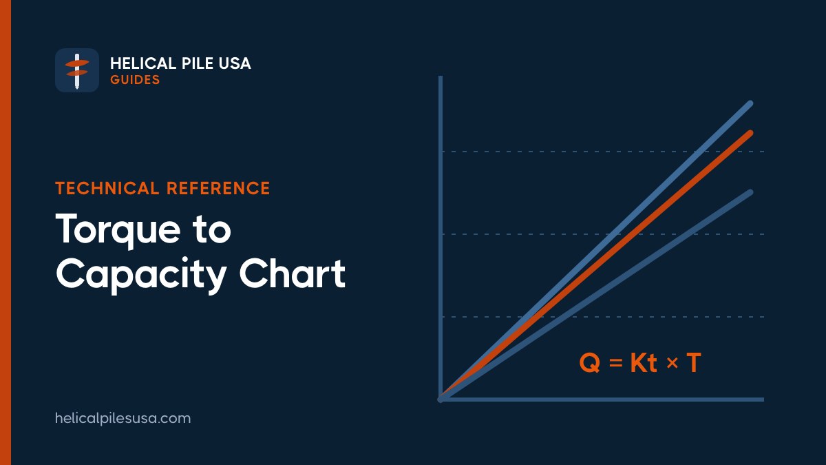

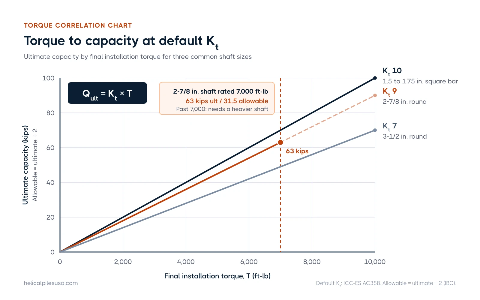
A helical pile's ultimate capacity is estimated by multiplying its final installation torque by a torque correlation factor: Qult = Kt × T. Under ICC-ES AC358, the default Kt is 10 ft-1 for 1.5 to 1.75 inch square bar, 9 for 2-7/8 inch round shaft, 8 for 3.0 inch round and 7 for 3-1/2 inch round. So a 2-7/8 inch pile installed to 7,000 ft-lb has an ultimate capacity of about 63,000 lb, or 31,500 lb allowable at a factor of safety of 2. The chart below runs those numbers for 3,000 to 10,000 ft-lb.
Key takeaways
- The formula: Ultimate capacity (lb) = Kt (ft-1) × final installation torque (ft-lb). Allowable capacity is half of that for permanent structures.
- Default Kt values: 10 for 1.5 to 1.75 inch square, 9 for 2.875 inch round, 8 for 3.0 inch round, 7 for 3.5 inch round, per AC358.
- Bigger shaft, lower Kt: Larger shafts need more torque to reach the same capacity, so Kt drops as diameter grows.
- Torque is measured, not guessed: Crews read differential hydraulic pressure across the drive motor or use an inline electronic torque transducer.
- The shaft sets a ceiling: You cannot install past the manufacturer's rated maximum installation torque, which caps the capacity you can prove by torque.
- Load tests override defaults: Static tests to ASTM D1143 (compression) and ASTM D3689 (tension) verify Kt or justify a higher one.
How the torque correlation works
As a helix plate screws through soil, it shears the ground around it. The harder the soil, the more torque the drive head needs to keep the pile advancing. That resistance acts like a continuous field test of the soil at the helix depth, which is why final installation torque tracks capacity so well.
The method entered the engineering literature in 1989, when Hoyt and Clemence analyzed close to 100 load tests from 24 sites on shafts from 1-1/2 to 3-1/2 inches and found torque predicted capacity more consistently than theoretical bearing methods, according to Hubbell's history of the Kt factor. A later compilation by CTL Thompson drew on more than 800 AC358 load tests, and very few results fell below a factor of safety of 2.
The International Building Code allows torque correlation as one of four ways to set ultimate capacity in Section 1810.3.3.1.9. The allowable axial load is Pa = 0.5 Pu, where Pu is the least of: helix bearing area times soil bearing capacity, a well-documented torque correlation, a load test result, or the structural capacity of the shaft (see the code text reproduced in Ram Jack's IBC design chapter). That 0.5 multiplier is the factor of safety of 2 used throughout this guide. For broader code context, see our guide to helical pile permits and building codes.
Default Kt factors by shaft size
The IBC does not print Kt numbers itself. The defaults come from AC358, the ICC-ES acceptance criteria that manufacturers use to get evaluation reports. These values apply to "conforming" systems, which must meet a list of geometry rules in AC358 Table 3: true helix plates 8 to 14 inches in diameter and 3/8 to 1/2 inch thick, a 3 inch pitch (plus or minus 1/4 inch), helices spaced 2.4 to 3.6 diameters apart, and installation at under 25 rpm.
| Shaft | Default Kt (ft-1) | Torque for 10 kips allowable (FS 2) | Torque for 30 kips allowable (FS 2) |
|---|---|---|---|
| 1.5 to 1.75 in. solid square bar | 10 | 2,000 ft-lb | 6,000 ft-lb |
| 2-7/8 in. (2.875 in.) OD round | 9 | 2,222 ft-lb | 6,667 ft-lb |
| 3.0 in. OD round | 8 | 2,500 ft-lb | 7,500 ft-lb |
| 3-1/2 in. (3.5 in.) OD round | 7 | 2,857 ft-lb | 8,571 ft-lb |
For other shafts inside the AC358 range (square bar from 1.5 to 3.0 inches, round shafts from 2.125 to 4.5 inches OD), a manufacturer's tested Kt is capped by the formula Kt = 22.285 × deff-0.9195, rounded down to the nearest 0.5. Plugging in a 4.5 inch shaft gives a cap of about 5.5. Outside that size range, AC358 says torque correlation is out of scope, and capacity is set by bearing calculations and load tests. Not sure what shaft you have? Our helical pile shaft sizes chart lists common sizes by use.
Helical pile torque to capacity chart
Each cell shows ultimate capacity / allowable capacity in kips (1 kip = 1,000 lb), using allowable = ultimate ÷ 2.
| Final torque (ft-lb) | Kt 10 (square bar) | Kt 9 (2-7/8 in.) | Kt 7 (3-1/2 in.) |
|---|---|---|---|
| 3,000 | 30 / 15 | 27 / 13.5 | 21 / 10.5 |
| 4,000 | 40 / 20 | 36 / 18 | 28 / 14 |
| 5,000 | 50 / 25 | 45 / 22.5 | 35 / 17.5 |
| 6,000 | 60 / 30 | 54 / 27 | 42 / 21 |
| 7,000 | 70 / 35 | 63 / 31.5 | 49 / 24.5 |
| 8,000 | 80 / 40 | 72 / 36 | 56 / 28 |
| 10,000 | 100 / 50 | 90 / 45 | 70 / 35 |
Read this chart with the shaft's torque rating in mind. A row only applies if the shaft can actually take that torque without twisting off. For example, the CHANCE RS2875.203 data sheet rates that 2-7/8 inch shaft at 7,000 ft-lb, which is exactly why Hubbell lists it at 63 kips ultimate and 31.5 kips allowable. The 8,000 and 10,000 ft-lb rows in the Kt 9 column need a heavier wall or a stronger shaft.
Working it backward: required torque
Engineers usually start with the load and solve for torque: T = (design load × 2) ÷ Kt. In one of Supportworks' published design examples, a 30 kip working load on a 2-7/8 inch pile needs 60 kips ultimate, so 60,000 ÷ 9 = 6,667 ft-lb, specified as a minimum of 6,700 ft-lb. A second example puts a 40 kip compression load on a 3-1/2 inch shaft: 80,000 ÷ 7 = 11,428 ft-lb, rounded up to 11,500. That final torque target goes on the drawings, and the installer keeps advancing the pile until it is reached at or below the design depth. For how depth and torque interact on site, see how deep helical piles go.
How helical drive head torque is measured
Helical piles are installed with a hydraulic drive head (a planetary gearbox driven by a hydraulic motor) mounted on a skid steer, mini excavator or excavator. Torque at the shaft cannot be read directly off the machine, so crews use one of these methods, described in Supportworks' technical note on monitoring torque:
- Dual pressure gauges: One gauge on the feed line to the drive head and one on the return. The return pressure is subtracted from the feed pressure to get differential pressure, which is converted to torque using the gear motor multiplier (GMM) from the drive head maker. Most drive head makers publish a pressure-to-torque chart, sometimes called the motor curve.
- Single feed-line gauge: Faster but less accurate. Ignoring back pressure on the return side tends to overstate torque, which overstates capacity.
- Differential pressure gauge: Both lines plug into one gauge body whose dial reads torque directly. Because the dial is built around one GMM, each drive head needs its own gauge.
- Electronic pressure indicators: Transducers on the feed and return lines feed a digital display that converts pressure drop to torque. Some log data or connect by Bluetooth.
- Inline electronic torque transducers: A strain-gauge unit sits between the drive head and the pile, measuring true torque in real time with depth and angle logging. A calibrated transducer can also be used to check pressure-gauge setups.
At a minimum, torque should be recorded at the end of each lead and extension section. For critical work, readings every foot build a soil strength profile. For tension piles and tiebacks, the same note recommends readings every foot over the last 3 to 5 feet, with the average used to compute capacity. If you are hiring, ask what device the crew uses and when it was last calibrated. Our guide on the helical pile installation process covers what a torque log should look like.
Why manufacturers publish their own Kt
The AC358 defaults are starting points. Any manufacturer that wants a Kt recognized in an evaluation report has to prove it with full-scale field load tests in compression and tension. For a conforming system, the correlation is accepted only if every tested ultimate capacity exceeds the predicted allowable capacity and the average ratio of tested ultimate to predicted allowable is at least 2.0. If the product fails that check or falls outside the Table 3 geometry rules, it is "nonconforming" and needs a larger test program to set its own Kt. Separate correlations are required for each shaft geometry and each helix style.
That is why published values differ from brand to brand. Ram Jack's design manual lists default Kt of 10, 9, 7 and 6 for its 2-3/8, 2-7/8, 3-1/2 and 4-1/2 inch shafts, paired with torque ratings of 4,000, 8,000, 14,000 and 23,000 ft-lb. Always use the Kt and torque rating in the specific product's evaluation report, not a generic table. You can compare brands on our helical pile manufacturers page, including CHANCE, Ram Jack and Foundation Supportworks.
Limits of the torque method
- Maximum installation torque: IBC Section 1810.4.11 requires piles to be installed to the depth and torque criteria set by the design professional, and the applied torque may not exceed the manufacturer's rated maximum (code text). Overtorquing can twist the shaft or damage couplings.
- Shaft and helix strength: Under Section 1810.3.3.1.9, capacity is the least of soil, torque, load test and shaft values. A high torque reading does not help if the shaft buckles or the helix plate punches through.
- Tension vs compression: The original Hoyt and Clemence tests were in tension, and later studies found tension capacity 16 to 33 percent lower than compression, per Ram Jack's manual. Many designers use the same Kt for both, which is conservative in compression.
- Large shafts: The correlation is generally accepted up to about 4.5 inch OD. Bigger shafts are designed by theory and verified by load testing.
- Not the only check: Hubbell itself advises against relying on torque alone, and recommends pairing it with a bearing capacity calculation from soil data.
When load testing is required
A static load test gives the actual ultimate capacity at your site instead of a correlation. Compression tests follow ASTM D1143 and tension tests follow ASTM D3689. AC358 product testing uses the quick load test procedure in Section 10.1.2 of each standard. Common reasons to test on a project include:
- The engineer wants a higher Kt (a more aggressive design) than the default allows.
- Design loads exceed what the allowable stresses in IBC Section 1810.3.2.6 would support.
- The design load for a pile is in doubt, for example in variable fill, organics or very soft clay.
- The product is nonconforming or the shaft is outside the AC358 torque correlation range.
- The building official or project specification calls for it.
For a typical house, deck or porch, the engineer of record usually relies on torque correlation plus a documented torque log. Commercial projects with heavy column loads or tension tiebacks are where pre-production test piles are most common.
Homeowner version and finding an installer
This chart is the technical reference. If you just want to know whether helical piles can carry your house, deck or addition, start with our plain-language guide: how much weight can a helical pile hold. Spacing also changes how much each pile carries, so see how far apart helical piers need to be.
When you get quotes, ask each contractor for the shaft size, the Kt they are designing to, the target final torque, and whether they will hand over a signed torque log. You can find a helical pile installer in your state or province in our directory, and our checklist on how to hire a helical pile contractor covers the rest.
Frequently asked questions
What is the Kt factor for a helical pile?
Kt is the empirical ratio of ultimate capacity to final installation torque, in ft-1. AC358 defaults are 10 for 1.5 to 1.75 inch square bar, 9 for 2-7/8 inch, 8 for 3 inch and 7 for 3-1/2 inch round shaft.
How do you convert torque to capacity for a helical pile?
Multiply final installation torque in ft-lb by Kt to get ultimate capacity in pounds, then divide by 2 for allowable capacity. For example, 6,000 ft-lb × 9 = 54,000 lb ultimate, or 27,000 lb allowable.
What factor of safety is used for helical piles?
The IBC sets allowable axial load at 0.5 times ultimate capacity, which is a factor of safety of 2. That is the standard for permanent structures.
Can you just keep adding torque to get more capacity?
No. Torque is limited by the shaft's rated maximum installation torque, and the IBC forbids exceeding it. To carry more load, the design moves to a larger shaft, more piles or a load-tested Kt.
Is torque correlation accurate in all soils?
It is reliable for conforming piles in most soils, but it is an empirical average. Engineers check it against soil-based bearing calculations, and use load tests where soils are variable or loads are critical.
How is torque read on a hydraulic drive head?
Most crews measure differential pressure across the drive motor and convert it to torque with the manufacturer's gear motor multiplier. Inline electronic torque transducers give a direct reading and can calibrate gauge setups.
Subscribe to our weekly email newsletter
Industry news, featured projects, new products, and installer spotlights from across the helical pile industry, delivered to your inbox.


Latest articles

Get the Helical Pile Industry Brief
New installers, manufacturer news, cost updates, and fresh guides for the U.S. and Canadian helical pile industry. Short, occasional emails. Unsubscribe any time.
