

Helical Pile Load Testing: ASTM Methods, Proof and Verification
Helical pile load test guide: ASTM D1143, D3689 and D3966, proof vs verification test loads, quick test procedure, setup and acceptance criteria.

A helical pile load test pushes or pulls on an installed pile with a hydraulic jack and records how far it moves at each load step. The results show whether the pile can carry the design load with an adequate margin. Compression tests follow ASTM D1143, tension tests follow ASTM D3689 and lateral tests follow ASTM D3966. Pre-production (verification) piles are typically taken to 200% of the design load, and production (proof) piles to 133% or 160%, according to Hubbell's CHANCE engineering team.
Key takeaways
- Why test: Torque correlation is an empirical estimate. A load test is the only direct measurement of how a pile behaves in the soil on your site.
- The standards: ASTM D1143/D1143M-26 (compression), D3689/D3689M-25 (tension) and D3966/D3966M-25 (lateral) are the current editions on the ASTM store.
- Test loads: About 200% of design load for verification piles and 133% to 160% for proof tests on production piles.
- Acceptance: The common helical criterion is a net helix movement of 10% of the average helix diameter. The Davisson offset is another option, and the engineer of record picks the method.
- How many: The engineer sets the count, often one pile or a percentage of production piles. Testing at least one pile is commonly recommended on jobs with more than 50 piles.
- Tension is cheaper: A tension test needs one pile and cribbing. A compression test needs the test pile plus reaction anchors, usually four.
Why load testing matters when torque already predicts capacity
Most helical piles are sized with the torque correlation, Qult = Kt × T, where final installation torque stands in for soil strength. The method works well on average, but it is still a statistical fit. Hubbell estimates that designs based on Kt alone produce about 3 inadequate piles per 1,000, or roughly 0.3%, in its guide to conducting helical pile load tests. Our torque to capacity chart explains the default Kt values.
Load tests cover the cases where that estimate is weakest or where a better number pays off:
- Unusual soil: Layered profiles with dense and loose strata near the helix depth, or piles that refuse on rock, can make torque misleading. Hubbell says a compression test is essential in those cases.
- Tension versus compression: The original torque studies were tension tests, and later work found tension capacity 16 to 33 percent below compression capacity, according to Ram Jack's IBC design chapter.
- A higher site-specific Kt: Hubbell gives an example where testing supported a Kt of 15 against a default of 10. A higher factor means less torque, shorter piles or fewer piles.
The ASTM standards for pile load tests
All three methods cover deep foundation elements in general and set minimum requirements that a project specification can add to. Current editions on the ASTM store as of October 2026:
| Standard | Title | Current edition | Used for |
|---|---|---|---|
| ASTM D1143/D1143M | Standard Test Methods for Deep Foundation Elements Under Static Axial Compressive Load | D1143/D1143M-26 | Compression tests on piles that carry building loads down |
| ASTM D3689/D3689M | Standard Test Methods for Deep Foundation Elements Under Static Axial Tensile Load | D3689/D3689M-25 | Tension (uplift) tests on anchors, tiebacks and uplift piles |
| ASTM D3966/D3966M | Standard Test Methods for Deep Foundation Elements Under Static Lateral Load | D3966/D3966M-25 | Lateral tests for wind, seismic and solar racking loads |
Older documents cite earlier editions; AC358 (published April 2025) references D1143-20, D3689-22 and D3966-22. Check which edition your specification names.
Building code and AC358 requirements
IBC Section 1810.3.3.1.9 (helical piles)
The International Building Code sets the allowable axial load of a helical pile as Pa = 0.5 Pu. Pu is the least of four values: helix bearing area times the ultimate bearing capacity of the soil, a well-documented torque correlation, the ultimate capacity from load tests, and the axial capacity of the shaft. Ram Jack's design manual chapter reproduces the section and notes that the approved load tests are ASTM D1143 for compression and ASTM D3689 for tension.
IBC Section 1810.3.3.1.2 (load tests)
The general load test section, shown in the 2024 code text on UpCodes, requires a test where design compressive loads exceed those allowed by the code's allowable stresses, or where the design load of any deep foundation element is in doubt. At least one element must be tested in each area of uniform subsoil conditions. The allowable load cannot exceed one-half of the ultimate capacity of the test element, as assessed by a registered design professional.
Lateral loads (IBC 1810.3.3.2)
When lateral capacity is set by testing, the element is loaded to at least twice the proposed design working load. The allowable load is no more than one-half of the load that causes 1 inch of gross lateral movement, as quoted in the Ram Jack chapter above.
What AC358 requires
AC358 is the protocol manufacturers follow to earn an ICC-ES evaluation report. It qualifies products rather than projects, but engineers borrow its methods. Key points from AC358:
- Full-scale axial tests use ASTM D1143 and D3689 with the quick load test procedure (Section 10.1.2 of each standard).
- Maximum capacity is reached at plunging or when net deflection exceeds 10% of the helix diameter, whichever comes first. Net deflection is total deflection minus elastic shortening or lengthening of the shaft, and multi-helix piles use the average helix diameter.
- Torque is measured with a calibrated in-line indicator or a calibrated hydraulic motor, traceable to NIST.
- Tension test piles must have the top helix at least 12 times the largest helix diameter below the ground surface.
- A Kt value is verified only if every tested ultimate capacity exceeds the predicted allowable capacity and the average ratio of the two is at least 2.0.
- Lateral allowable capacity is one-half of the load that causes 1 inch of lateral deflection at the ground surface.
For how evaluation reports present these results, see our guide to ICC-ES evaluation reports for helical piles. For local permit practice, see helical pile permits and building codes.
When engineers and building officials ask for tests
In practice, the engineer of record decides. Hubbell notes tests are typical on larger commercial jobs, variable soil sites and where a site-specific torque correlation is wanted. Small jobs and residential underpinning usually rely on the IBC torque values instead, and on jobs that lift a structure each pile is effectively proof-loaded during the lift.
Verification tests vs proof tests
A verification test (also called a pre-production or sacrificial test) is run before production installation starts. Its job is to confirm the design assumptions, the target torque and the Kt value, and it is often taken to failure or close to it. A proof test is run on a production pile that will stay in service, so it stops well short of failure and simply confirms the pile meets the specified movement limits.
| Test type | When | Typical maximum load | Standard | What it proves | Pile reused? |
|---|---|---|---|---|---|
| Verification (pre-production), compression | Before production piles | 200% of design load | ASTM D1143 | Ultimate capacity, site Kt, design torque | Usually not |
| Verification (pre-production), tension | Before production piles | 200% of design load | ASTM D3689 | Uplift capacity and site Kt; often a conservative check on compression | Usually not |
| Proof (production) | During production | 133% or 160% of design load | ASTM D1143 or D3689 | That an installed pile meets movement limits | Yes |
| Lateral | Where lateral load governs | At least 2x design working load (IBC) | ASTM D3966 | Load at 1 inch of lateral movement | Depends on spec |
Test loads are from Hubbell and the IBC lateral section.
Quick vs maintained load procedures
ASTM D1143 describes three loading procedures, per the standard's scope: the quick test, the maintained test and the constant rate of penetration test. The quick test and constant rate test typically finish in a few hours. The maintained test uses larger load increments held for longer, so it takes longer. It gives more information on creep but a less precise failure load.
- Quick test (the helical default): Hubbell describes increments of 5% to 10% of the anticipated failure load, each held for at least 4 minutes at constant load, with movement read at the end of each hold. Loading continues until the pile has moved about 2 to 3 inches, then the pile is unloaded in about 4 steps to measure rebound. AC358 requires this procedure.
- Maintained test: Steps are tied to the design load and held until movement slows. One FHWA example, from the Central Artery/Tunnel project report, added 25% of design load every half hour and held the peak load at least an hour, until settlement over an hour was no more than 0.01 inch.
Bengt Fellenius, in The Static Loading Test (2015), favors about 20 equal increments with constant holds and no unload-reload cycles, which is close to the helical quick test.
As a pile creeps, hydraulic pressure drops and the pump must add fluid to hold the load, more so near capacity. Hubbell logs load and deflection every 30 seconds so any dropped load shows up, per its note on maintaining load during a test.
The test setup
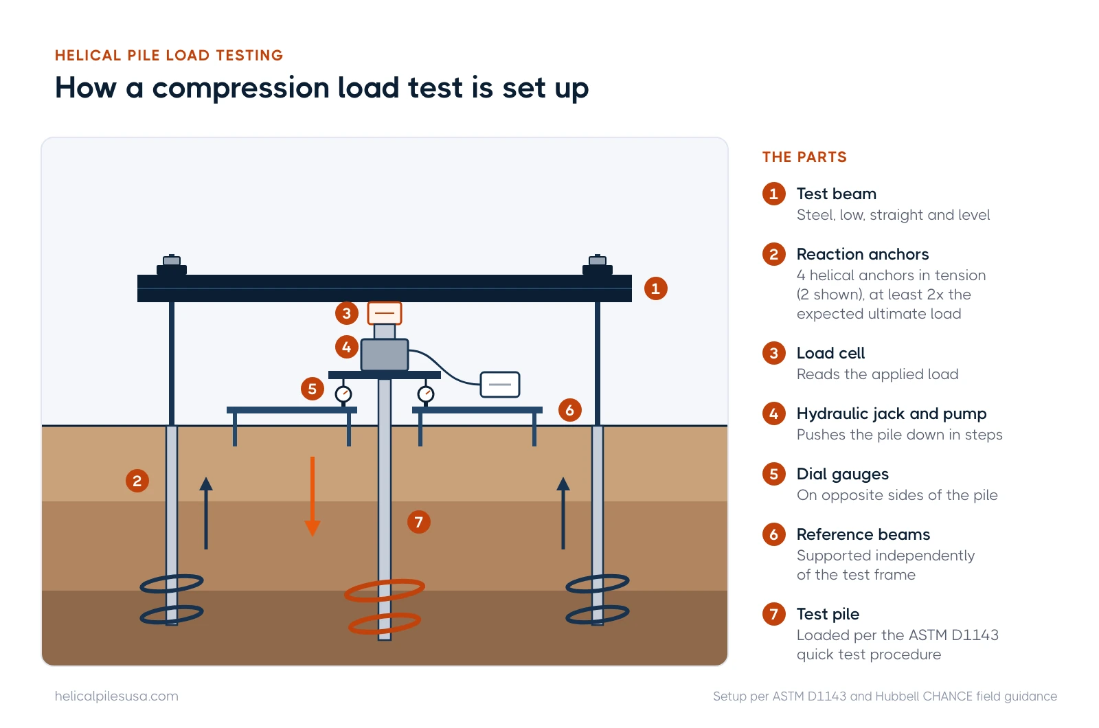
A compression test pushes against reaction anchors (extra helical piles loaded in tension) tied to a steel test beam over the test pile. The parts are:
- Reaction anchors: Hubbell's field note on compression testing calls for 4 vertical anchors with combined capacity at least double the test pile's expected ultimate capacity. Anchors are preloaded by tightening nuts on threaded rod at the beam.
- Test (load) beam: Low to the ground, straight and level, centered over the test pile. Misalignment bends the pile head; the same note describes a test stopped below 5,000 lb because a 2-anchor beam began to rotate.
- Hydraulic jack and pump: The jack sits on the pile cap and pushes up against the beam.
- Load cell or calibrated gauge: A load cell reads load directly. Without one, the jack, pump and pressure gauge are calibrated together as a system so pressure converts to load.
- Reference beams and dial gauges: Two reference beams supported independently of the test frame carry dial indicators on opposite sides of the pile, so the readings are not affected by the frame moving.
A tension test is simpler: the jack sits on a load beam supported by wood cribbing or mats on the ground and pulls the pile up. Only one pile is installed, compared with at least five for a compression test, which is why Hubbell calls tension testing the more cost-effective choice. It also tends to give a lower, conservative capacity than compression.
Acceptance criteria: 10% of helix diameter and the Davisson offset
A test answers the capacity question only once failure is defined. Two definitions are most common on helical projects.
10% of the average helix diameter
Under AC358 and Hubbell's recommendation, ultimate capacity is the load at which the helix plates have moved a net distance of 10% of their average diameter, or the load at plunging if that comes first. Net movement is the head movement minus the elastic shortening of the shaft (PL/AE). For a pile with 10 inch and 12 inch helices, the average is 11 inches, so the limit is 1.1 inches of net movement.
Davisson offset
Davisson's 1972 method draws the pile's elastic compression line (PL/AE) and offsets it by 0.15 inch plus the pile diameter divided by 120. The first load where the measured curve crosses that line is the limit load. For a 12 inch pile, the offset is 0.15 + 12/120 = 0.25 inch. Fellenius notes the method was fitted to an FHWA database of driven pile tests, so it is a convention, not a law of soil behavior. Hubbell lists Davisson, Brinch-Hansen 90% and Butler-Hoy as accepted alternatives; the engineer of record chooses.
Movement limits at design load
Specifications also cap movement at design load. Hubbell reports typical total deflection of 1/2 to 3/4 inch at design load, net helix movement of 1/4 to 1/2 inch at working load, and gross deflection of about 1 to 1-1/2 inches at ultimate geotechnical capacity. The owner or structural engineer should set the allowed movement before the test.
How to read a load-displacement curve
The result of a test is a plot of load (usually on the horizontal axis) against pile head movement (on the vertical axis, increasing downward). Reading it takes four steps:
- Find the straight early portion. At low loads the curve tracks close to the elastic line, which means the soil is carrying load with little permanent movement.
- Plot the elastic line and offset. Draw PL/AE for the shaft, then the offset line for your criterion (10% of average helix diameter, or Davisson's 0.15 inch + b/120).
- Read the crossing. The load where the measured curve meets the offset line is the ultimate capacity under that criterion. If the pile plunges first (movement keeps growing without added load), plunging load governs.
- Check the rebound. The unload curve shows how much movement was elastic and how much was permanent set.
Then apply the code: allowable load is no more than one-half of the ultimate. If the test pile was installed to a known torque, dividing the ultimate capacity by that torque gives a site-specific Kt to use for production piles. For capacity basics, see how much weight a helical pile can hold and the helical pile design guide.
How many tests, and what drives the cost
There is no single code count for helical projects beyond the IBC's one test per area of uniform subsoil when testing is required. Hubbell says the engineer of record typically specifies either a fixed number, such as one pile, or a percentage of production piles, such as 10%, and recommends testing at least one pile on any job with more than 50 piles. On commercial work, testing is usually carried as a line item in the bid.
We did not find a current, sourced price range for helical pile load tests, so we do not quote one. The main cost drivers are clear from the sources above:
- Test direction: Compression needs the test pile plus about four reaction anchors, a frame and more setup time. Tension needs one pile and cribbing.
- Test load: Larger loads need bigger beams, jacks and anchors.
- Procedure: A quick test takes a few hours; a maintained test runs longer.
- Who runs it: Independent testing firms, a licensed engineer's report and calibrated equipment all add cost.
Ask for a line-item quote naming the standard, maximum test load, reaction anchor count and acceptance criterion. Installed pile pricing is in our helical pier cost guide.
Finding a contractor who can run load tests
Not every installer owns a test frame. Ask for a sample test report, calibration certificates for the jack and gauges, and whether a third-party engineer will witness the test. See how to hire a helical pile contractor and the installation process, or find a helical pile installer in your state or province.
Frequently asked questions
What is the difference between a proof test and a verification test?
A verification test is run on a sacrificial pile before production to confirm capacity and Kt, typically to 200% of design load. A proof test is run on a production pile to 133% or 160% of design load to confirm it meets movement limits, and the pile stays in service.
Which ASTM standard covers a helical pile tension test?
ASTM D3689, Standard Test Methods for Deep Foundation Elements Under Static Axial Tensile Load. The current edition is D3689/D3689M-25.
Does a house need a helical pile load test?
Usually not. Residential and small projects generally rely on the IBC torque correlation, and a full-scale test is reserved for larger jobs, variable soil or when the building official or engineer finds the design load in doubt.
What deflection is acceptable in a helical pile load test?
The engineer of record sets it. Typical values are 1/2 to 3/4 inch of total movement at design load, and ultimate capacity is often defined at net helix movement of 10% of the average helix diameter.
Can a load test increase the capacity I can use?
Yes. A test can justify a site-specific Kt higher than the default, which can reduce installation torque, pile length or pile count.
Estimate capacity from torque with our free helical pile tools, or start with what a helical pile is.
Last reviewed October 2026 by the Helical Pile USA editorial team. Found an error? Tell us.
Subscribe to our weekly email newsletter
Industry news, featured projects, new products, and installer spotlights from across the helical pile industry, delivered to your inbox.


Latest articles

Get the Helical Pile Industry Brief
New installers, manufacturer news, cost updates, and fresh guides for the U.S. and Canadian helical pile industry. Short, occasional emails. Unsubscribe any time.
